Image Galleries
Featured Article
 Electron Multiplying Charge-Coupled Devices (EMCCDs)
By incorporating on-chip multiplication gain, the electron multiplying CCD achieves, in an all solid-state sensor, the single-photon detection sensitivity typical of intensified or electron-bombarded CCDs at much lower cost and without compromising the quantum efficiency and resolution characteristics of the conventional CCD structure.
Product Information
Interactive Flash Tutorials
Median Filters for Digital Images
The median filter is an algorithm that is useful for the removal of impulse noise (also known as binary noise), which is manifested in a digital image by corruption of the captured image with bright and dark pixels that appear randomly throughout the spatial distribution. Impulse noise arises from spikes in the output signal that typically result from external interference or poor sensor configuration.
This interactive tutorial explores the removal of impulse noise from a digital image using the median filter, and how the application of this and related filtering techniques affect the final appearance of the filtered image. The tutorial initializes with a randomly selected specimen (imaged in the microscope) appearing in the left-hand window entitled Specimen Image. Each specimen name includes, in parentheses, an abbreviation designating the contrast mechanism employed in obtaining the image. The following nomenclature is used: (FL), fluorescence; (BF), brightfield; (DF), darkfield; (PC), phase contrast; (DIC), differential interference contrast (Nomarski); (HMC), Hoffman modulation contrast; and (POL), polarized light. Visitors will note that specimens captured using the various techniques available in optical microscopy behave differently during image processing in the tutorial.
Adjacent to the Specimen Image window is a Filtered Image window that displays the image that has been filtered by a method selected in the Choose A Filtering Method pull-down menu. To operate the tutorial, select an image from the Choose A Specimen pull-down menu, and then select a filtering method from the Choose A Filtering Method pull-down menu. A choice between grayscale and color images is available in the tutorial, and the desired image collection may be selected by clicking on the Grayscale Images control or the Color Images control. The number of iterations entered into the text field located between the two sliders determines the number of times that the microscope image will be filtered by the selected processing method. Clicking the mouse cursor on the blue buttons appearing to the left and right of the iteration number text field will increase or decrease this value by one. The iteration number can also be adjusted by clicking on the text field input box, editing the number with the keyboard, followed by depressing the Enter key. The degree of artificial noise added to the specimen image can be increased or decreased by adjusting the Noise Level slider. The noise level added to the image is displayed directly above the slider as a percentage of the total number of image pixels. Visitors should examine the effects of the various filtering methods on the visual quality of the image after filtering, while varying the level of noise and the number of filtering iterations.
Potential sources of noise in digital imaging systems are quite numerous and can seriously degrade captured image quality. The amounts and types of noise that occur in the camera output signal are determined primarily by the camera sensor and its calibration, as well as by the electrical components in the camera itself, and auxiliary electronic devices used in conjunction with the camera. Common sources of radio frequency spikes and noise pulses include transformers, lamps, and other electronic devices. In some cases, it is possible to remove or minimize the effects of the most serious sources of noise through careful calibration and shielding of equipment. In other cases, it is preferable to filter such noise from images in the post-processing stage. The median filtering algorithm is a simple and viable approach to removing impulse noise from digital images.
In the tutorial, several noise-filtering algorithms are available for comparison. The first algorithm is 3 x 3 Box-Averaging algorithm, which is a linear filter unrelated to the median filter. This filter computes an unweighted average of the pixel brightness values in a 3 x 3 neighborhood surrounding each pixel in the specimen image. The average value then defines the pixel brightness for each corresponding pixel in the filtered image. The box-averaging algorithm can be formulated as a convolution operation on the pixels of the original specimen image with the kernel:
| 1 1 1 |
| 1 1 1 |
| 1 1 1 |
The box-averaging filter is clearly unsuccessful in removing impulse noise from the original image in the tutorial. Its main effect is to distribute the intensity of the impulse noise spikes among the surrounding pixels, making the noisy pixels slightly less noticeable, but not eliminating them. For images containing a substantial amount of noise, the filtered image sometimes appears no better, and often quite worse, than the original. This effect is compounded by the fact that pixel averaging blurs the image, resulting in a significant loss of high-frequency image detail. In addition, brightness differences across boundaries are reduced by pixel averaging and, in some cases, boundaries can appear shifted spatially.
The median filter, when applied to grayscale images, is a neighborhood brightness-ranking algorithm that works by first placing the brightness values of the pixels from each neighborhood in ascending order. The median or middle value of this ordered sequence is then selected as the representative brightness value for that neighborhood. Subsequently, each pixel of the filtered image is defined as the median brightness value of its corresponding neighborhood in the original image.
The median filter for color images operates differently from the grayscale median filter. Since each pixel in an RGB color image is composed of three components (red, green, and blue), it is not useful to rank the pixels in the neighborhood according to brightness. Instead, the color median filter works by comparing each pixel's color to that of every other pixel in the neighborhood. The pixel whose red, green, and blue components have the smallest sum of squared differences from the color coordinates of its neighbors is then chosen to replace the central pixel of the neighborhood.
Because the impulse noise spikes are much brighter or darker than their neighboring pixels, they generally wind up at the top or bottom of the brightness ranking for a neighborhood of input pixels. As a consequence, those values displaying brightness extremes generally lie far from the median value and are removed by the filter. The typical effect of median filtration on a noisy digital image is a dramatic reduction in impulse noise spikes. In addition, the median filter tends to preserve brightness differences across signal steps, resulting in minimal blurring of regional boundaries. The median filter also tends to preserve the positions of boundaries in an image, making this method useful for both visual examination and measurement. In addition, application of a median filter may be repeated until there are no further changes in the filtered image, which produces an image with nearly uniform regions that are effectively classified for segmentation. When used in this way, the median filter works like a maximum expectation restoration, or a Kuwahara filter.
The median filter is less effective in removing Gaussian or random-intensity noise, because the noisy pixels in this case are less likely to differ in brightness from the pixels in the neighborhoods they occupy. Also, the median filter can remove impulse noise from a neighborhood only if the noisy pixels occupy less than one half of the neighborhood area. Utilization of larger neighborhood masks or multiple applications of the median filter (with smaller neighborhood masks) can improve noise suppression at the expense of a loss in image detail. With repeated applications of the filter, a contouring effect similar to posterization can occur, where pixel brightness values are leveled across regions (a region in this sense is a group of pixels having similar brightness values). In the tutorial, these effects can be seen with repeated applications of the 3 x 3 and 5 x 5 median filtering algorithms (N x N Median with the Neighborhood Size slider set to 3 or 5).
Another filtering algorithm available in the tutorial is the Gaussian Filter. As with box averaging, Gaussian filtering is a linear convolution algorithm unrelated to the median filter. A Gaussian filter employs a convolution kernel that is a Gaussian function, which is defined in Equation 1. The parameter s in Equation 1 denotes the sigma value or standard deviation of the Gaussian function. When used for generating a convolution kernel for a Gaussian filter, the sigma value allows the user to make fine adjustment to the amount of spatial averaging that occurs in the image. Gaussian filtering with a sigma value equal to the radius of the neighborhood used in the median filter gives about the same degree of noise reduction but blurs edges much more than the median (and less than box averaging). When the Gaussian Filter option is selected from the Choose A Filtering Method pull-down menu, the Number of Iterations control panel will be replaced by a Standard Deviation slider that allows the user to adjust the standard deviation in pixels of the Gaussian kernel used to filter the image.

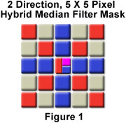
Some loss of image detail can occur from only a single application of the median filter. For a wide-bandwidth sensor, extreme brightness values might represent a valid signal pulse, but they would be rejected by the median filter. Signal suppression of this sort can result in a loss of grayscale resolution in the filtered image. Another concern in the application of the median filter is the shape of the neighborhood mask. A square-shaped mask can erode the corners of rectangular objects, while a cross-shaped neighborhood mask will leave corners intact. This observation has lead to the development of a hybrid median filter, which is a multiple-step brightness-ranking algorithm. For the two direction, 5 x 5 hybrid median filter included in the tutorial, the median brightness values of the neighbors forming an "X" shape are computed, along with the median brightness values of the neighbors forming a "+" shape, as illustrated in Figure 1.

These two brightness values, along with the brightness value of the central pixel of the neighborhood, are then placed in ascending order. The median value of the three resulting pixels then defines the brightness level of the filtered pixel. A hybrid median filter has the advantage of preserving corners and other features that are eliminated by the 3 x 3 and 5 x 5 median filters. With repeated application, the hybrid median filter does not excessively smooth image details (as do the conventional median filters), and typically provides superior visual quality in the filtered image.
Contributing Authors
Kenneth R. Spring - Scientific Consultant, Lusby, Maryland, 20657.
John C. Russ - Materials Science and Engineering Department, North Carolina State University, Raleigh, North Carolina, 27695.
John Childs and Michael W. Davidson - National High Magnetic Field Laboratory, 1800 East Paul Dirac Dr., The Florida State University, Tallahassee, Florida, 32310.


